Friday, March 22, 2013

More power!!!!


When I started planing my build I intended to use the external Rotax alternator, since the internal PMG only produces up to 18 amps. (Hello, electrically heated seats!!) However, as I got to know the SeaRey I realized that it had a weight problem, and decided to reduce the “goodies” to try to keep the electrical load within the 18 amp limits of the PMG. Good practice says you should limit your electrical load to 80% of the generator output, and the 914 manual recommends that if your aircraft requires loads above 12-15 amps you should use the external alternator. (Goodbye, electrically heated seats...)

While cutting the panel Jim showed me the external alternator he was installing on another aircraft. It was smaller than I thought, and only 8#. Of course, in addition to those 8# there is the wiring, etc it adds to the airplane.


As we continued cutting the panel we talked more about the pros and cons of adding the external alternator vs the weight penalty. The generator on the Rotax 914 is a “permanent magnet generator”, which means the magnets are fixed to the outside of the engine, the engine flywheel acts as the armature, and the rotation of the engine directly produces the electrical current for the plane.


Since both fuel pumps are electrically powered, as the manual states “In all cases the electrical system design should assure that no single failure mode (IE: alternator, battery, voltage regulator) causes both fuel pumps to stop. Careful design consideration must be given towards this issue!

While it would take a lot to cause a PMG to fail, Jim led me down the primrose path by asking me what I intended to do when I started flying Osp. “A lot of landings!!” I replied. We then discussed the power output of a generator, that it only developed power when at a higher rpm, and the lower the rpm, the lower the electrical output. As we all know, when in the pattern full power is used for takeoff but once at altitude power is reduced for level flight on the downwind, and further reduced for descent and landing, resulting in lower generator electrical output, and fewer amps for the system.

So while in the pattern, what's going on? Radio calls are being made and received, nav/strobe/landing lights are on, power is being used by the Skyview, but most importantly-the electric landing gear is being cycled, putting a high load on the electrical system.


The SeaRey is the only retractable gear aircraft I have ever flown that does not have a backup gear extension system, and it's kept me up many times at night. It's an elegant, yet simple system using dual electric motors for main gear extension/retraction and a garage door spring for tailwheel retraction (slaved to the left gear actuator for extension). But since it uses separate gear actuators, a bad day could see you with the gear stuck up or down, and a real bad day (like a failed connection ) could leave you with one gear up and the other one down, and few good alternatives.

More realistically, when doing pattern work the combination of low electrical power output and high electrical demand might end up inadvertently draining the battery, leaving you without enough power to extend the gear. While you could go fly around and charge up the battery, the SR has a narrow weather window, and if the winds or weather were kicking up, that might not be a good option.

End result, I'm reversing my decision not to go with the external 40 amp (Hello, electrically heated seats!!) alternator, and will be adding it to Osp.

Thursday, March 14, 2013

Travels with Puff

In case you haven't heard, Richard's book about his adventure with Puff is now available from Amazon, or even better, from your local independent bookstore


"Lasers" (but no sharks)

So what do you do with leftover veneer????


I needed some green and blue plastic labels for the Water and Ground gear warning lights, and while at Bay Engraving looking at the trophies I thought "Hmmmmm...." Talked with Kurt and a week later


I had him laser etch the labels in both light and dark sections of the scrap, which meant G & I got to play Scrabble with them and debate what looked best where.


Plus it looked different in the light of day the next morning, and after having some stain applied to the extras to test. I decided the dark background with dark lettering was just too dark to see, so we went with light overall.


Finally I taped them to the panel, sprawled out in the living room in SeaRey flying position and did some more Hmmmm'ing.


One of the hardest things was to decide the placement, above or below the switches. In some cases I didn't have a choice, in other cases after it was all done I realized small changes that would have made it look better. Oh well, nothing got put in the wrong place or upside down, so it's all good. 


Lots of clamps hold small pieces of cheap Harbor Freight straightedges I cut up and fixed in place.


Upon seeing a new airplane, most people immediately head to the cockpit and check out the panel ("Hey kid, want to look in the cockpit?"). I know Osp is going to gather attention because there aren't too many SeaReys up here (yet!), and for my own pride of building I wanted her panel to look beautiful, so I was pretty hesitant about this part.


We thought about some very thin doublestick tape, but decided against it in favor of a firmer glue attachment. This is a little CA (superglue) gel that was given to me as a sample to try a while back but never got around to using. Experimenting, I found the first small amount would soak into the paper backing, then stabilize and a tich more could be applied for the bond. It took a little practice to find the perfect amount that gave a bond but did not seep out, and a couple spots needed a little work with a knife point and/or sandpaper when it was all done, but overall it worked fantastic. If I was going to do it again, I'd probably use 30 min epoxy, though.


The other good thing about the IC-Gel was that it did not set up right away, but gave about 20-30 seconds before bonding. This was perfect because I could still make small adjustments, not so perfect because a couple parts moved slightly after placement. I had drawn some small pencil marks, but they would be covered when I put the piece down, and I thought the glue would adhere instantly. Since it turned out it took 20-30 seconds for the CA to set up, I wish I had used the pencil marks and 30 min epoxy, I could have made small changes to fine tune the layup after putting the piece down. Then again, in those 30 minutes the piece might have moved completely out of position and left a glue smear, sooo.....


The usual stack of gloves...


Followed by my old friend, the vacuum bag. I didn't pull a heavy vacuum, just enough (~20") to give a gentle but firm press for a couple hours.


The upper left Water is one that got away from me, about 1/32" off nominal above the alignment with the warning light, and the bottom light labels are off ~1/64" from left-right. I know, small things and probably won't be noticed, but one strives for perfection. And again, by blind luck I only trimmed 3/4" off the bottom, which was the perfect amount.


The rest came out just beautiful. Can't wait to see Gordon work his stain and varnish magic on it.


The Aux Power and Headset on the right wing are examples of seeing what I should have done after it was too late. Instead of aligning the bottom of the labels, I should have aligned the tops and stepped the Aux Power label down above the power socket. And Yes, as I was typing this I had to get up and fiddle with it a little to see if I could lift the Aux Power label up and reposition it. Not a chance, I'll have to live with it.


I thought about trying to remove them and going for a redo, but I remembered a story (and G told me a similar one) that one should always put a small flaw in your work that only you know about, to remind yourself that you are not perfect and to stay humble. I'm nowhere near good enough to have to intentionally put flaws into my work to stay humble, I find enough flaws as it is.


Now, about those glovebox hinges....

Wednesday, March 6, 2013

Brace for impacts

Back home, and it was time for final trimming and shaping.

The hull not only tapers from top to bottom, but allowances must be made at the hull/panel junction for any flexing as a result of hard landings or water impacts. The edges were brought in about 1/8”, and a D cell battery made a fine radius for the corner.


We had left the panel oversized, and Jim had drawn a max amount that could be trimmed off the bottom while allowing for an aluminum brace to be ran along the edge. Sitting in the cockpit I scrunched and wiggled and bent my legs around, looking to see how much room I needed vertically and laterally. Aesthetically, I wish I had made the wing panels deeper for more of an LSX style corner panel triangle, but that was the limit of my mold. “On my next SeaRey......”


While Jim said I could cut up to 1 1/4” from the bottom, I looked at the margin underneath the MFD and decided that it would bring the reinforcement brace too close to the base of the Skyview for my taste, and that trimming off another 3/4” would be enough. When we made the instrument cutouts the tape had served well to keep the veneer from splintering, so I ran another line of blue tape before measuring, marking, checking twice and cutting. I'm also glad I did not do the center console, it's nice to have the room to wiggle my feets.


First I cut the broad swatch of the base, then sketched the step from the wing to the center panel. I was worried that each side would be different, so after sketching them I used a small protractor to check the angle. Surprisingly, both were within a few degrees of each other, near 45 degrees. There's some meaning to that, I’m sure, but I’ll leave the magic of a 45 to others to explain. 


As usual, my Dremel stylus tool sanded the curve, with a little fine tuning once inside. The grain of the veneer at the base of the panel is at an angle, and it's sometimes difficult to overcome the optical illusion that I’m cutting my lines off-line, when I know they're correct.


Tape removed, time to sit back, relax and enjoy the work. One surprise was the solid, woody, almost sensual *thunk* the switches make I've not heard in other SeaReys, I'd like to think the panel has something to do with it.

Later a friend stopped by and pretended to wipe the spittle from the panel, telling me to not make such a mess when I was sitting making  “Pbbbbttttttt, pbbbbttttttt." airplane noises. Ummm... guilty, except for the spittle. 


A lousy photo, I was trying to sneak it in, but Merrill Wien stopped by to check on my progress, and share a tale of flying C-119 Boxcars in a classified program to retrieve Corona spy satellite capsules in midair. Merrill is writing his biography, and I can't wait to hear the stories he's putting down about his family's life and his flying career. I’m lucky I’ve gotten to know him.


In the meantime Mike dropped off his nosedeck, he's going to have Jim install his “Megahatch” and hitched a ride with mine. Jim will integrate my panel and nosedeck into one unit while  he installs the avionics/electrical.


Trimmed to final size and shape, the panel is very flimsy along the bottom edge, and by the time all the avionics are added in it's carrying a considerable load. A piece of 3/4” 6061-T6 takes care of the flexing and reinforces the bottom, it got trimmed for switches and the backup fuel pump circuit breaker.


I did a test with some scrap to see if resin alone would hold the angle to the panel, and the test held fine but I decided to add a half dozen #6 stainless steel screws too. Note the two center screws are vertically aligned with the radio mounts, the back of the radio stack will mount into these screws.


The screws also served to hold the strip in place while the West Systems 205 set up. Note how close to the MFD the reinforcing strip is, I’m glad I only trimmed 3/4” off the bottom of the panel.


I left the screws in place for about 3 hours, then gently removed them so they would not become permanently attached and replaced them with clamps for the final setup overnight. I did get a couple small bits of epoxy leakage around two of the screws, nothing that a swipe with the sandpaper didn't easily fix.


Before I left for a trip this morning I took the clamps off, the epoxy will have a few good days to finish setting up while I'm gone. Hopefully the labels will be done when I get back, and I'll try to figure out the glovebox hinging.

Saturday, March 2, 2013

Panel cutting and mounting.


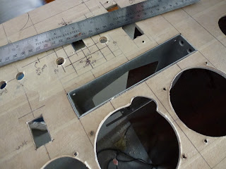
After Jim received the panel he covered it with masking tape to protect it, and transferred the equipment locations over. Quite a few hours of work there to make sure things lined up, and he made small shifts to some items to make it more aesthetically pleasing.


What looks like a small object from the front may be deceptively large behind the scenes. From top to bottom: a switch, circuit breaker, and start switch all have a considerable amount of hardware behind their small display face.


The vibration triggered Hobbs meter eliminates the need to run a wire to the oil pressure in the engine, so the cover plate is actually bigger than the actual unit.


In the old days engineers would actually make cockpit mockups-and in some cases even entire airplanes-out of wood to make sure systems fit, and instruments were readable and reachable by the pilots. Nowadays this is done all on a computer, and the Boeing 777 I fly was the first to be completely done on computer. In this case, Jim suggested we have the switches 1” apart, while I felt a minimal spacing of 3/4” was fine. A piece of cardboard substituted for the panel, and the 7/8” spacing turned out to be juuuuust right.


Those boxes are mostly full of air, with little tiny rectangles of electronics inside. Yes, I had to open each one up and look, even though I was like a dog looking at a TV. “Yup, that's a box.”


Oooooooo.... so fun to have my MFD in real life. Now put it down, Steve,


Wall-E? Nope, this is how Dynon updates their Skyview software. You download to a USB drive and plug it in. Cool.


This is really cool. I’m not going to do a lot of night flying, but I want the capability to stay up and watch the sunset, or if I want to get an early start to a trip and takeoff before sunrise, I want full night ops capability. This is a UMA light bezel, and instead of standard GA lighting via a post with a small light bulb inside, or lights behind a panel, this ring fits over the instrument and gives a soft, even illumination. Also note the airspeed indicator. Yeah, she's not going to be a speed demon, a real Osprey could probably outdive her.


A couple major changes were made-the Cessna split master switch was meant to be put into a thin sheet metal panel, and not into a 3/16” fiberglass/veneer laminate, so we decided to use separate toggle switches for the master and generator. After a long discussion and thinking it over, I also decided to go with the additional weight of the Rotax supplementary alternator. More on that in another post.


An interesting contrast going on outside Jim's hangar, as Valkaria Airport adds a row of hangars. Kinda fun to watch the little birds dance around the shovel as it digs, but...


The bad thing is all the dust and dirt it puts into the air that blows it's way into the hangar. Can's close the door or we'll steam.


One great suggestion he had was to talk me out of the green and blue mnemonic strips, and clean up the center panel area. Removing them gave an elegant look to the panel, and took away some cheesiness. I hated to ask it, but some things required Jim to redo his drawing.


It begins. Jim gets the feel for drilling the panel using the area inside the Dynon that will be scrap. Later he shows me a photo album, including an airplane he built years ago with a panel from a solid piece of teak wood. A quiet, soft spoken man, I'm learning a lot being around him.


I know that look- it means "I'm concentrating, leave me alone." I did.


After the drilling comes the cutting.


By this time it was mid-afternoon, and after getting back from doing a min rest Hong Kong flight I was finally feeling human again and ready to take my turn. I started my shift with the flap controller because it had a large cover plate that would (hopefully) cover up any screwups, but I didn't make any. It still makes me shake my head when I think that I'm being paid to fly big airplanes to far off places. I’m grateful, and worry that one day I’m going to wake up and be back waiting tables.


Gut check. My idea to cut the big holes for the analog instruments by starting with small ones inside and work our way out with a Dremel sanding drum, but Jim had some hole saws that he used in other panels. As always, a test cut was made in the Dynon area.


Excellent... it worked perfectly. Can he do it 3 times in a row?


I should know better than to think he freehands this stuff, a well used jig starts things off.


I couldn’t watch, so I grabbed a broom and swept the hangar while the holes were cut.


There's a reason sometimes you should hire professionals and then get out of the way. 3 perfect cuts later he uses the Dremel to grind out the opening for the altimeter setting knob.


Now the fun stuff: radio installation. If you look closely under the ruler you'll see the opening for the gear switch, and LED position lights, you can also see where I made a small adjustment and moved the Gear Alert light 1/8” from where I had previously decided. Small adjustment, and I felt silly doing it, but later when everything was done I was very happy I had changed it.


Took a little creative maneuvering to install the radio while I was making the final cuts.


While I was cutting, Jim made the radio mount brackets.


The final cut. I was terrified I was going to cut on the wrong side of the line, or something else dumb.


Perfect I started breathing again.


Final fittings.


Before


After


I had to sit a while and take it in. In all modesty, it's a beautiful panel, it was worth all the work and I can't wait to see it stained and varnished. Note that the bottom of the wing panels taper inward. When Gordon and I were fitting the panel we were getting worried because we thought those lines should be perfectly vertical, and I was racking my brain trying to figure out what I had done wrong. Turns out the hull DOES taper from top to bottom, and the panel should be like this. I did make an error in the panel, it's become a private joke between us and I don't think Jim is going to let me live it down, but I don't think even the sharpest observer will find it.


Got some reading to do before I can punch buttons, and I know I’ll have me share of finger fires until I get used to it. In the glass cockpit EMB-145 airliner I was a Check Airman in, I used to tell students that it took 100 hours to start to feel comfortable, and 3-500 hours to know what they were doing. Obviously, I’m going to have to learn this faster.


Wrap it,


Pack it,


And ship it. It was waiting for me when I got home the next day, but it had been opened and sloppily retaped. No damage, no note, nuthin' to explain why. Next will be final trimming/fitting, labels, and trying to figure out a way to cut and hinge a glove box in the space on the right side of the panel.


First concept


Reality


Dynon 10" Skyview with ADS-B, GPS, Mode S transponder.
PAR100EX radio
ACI gear alert system