December, 2012 addendum
It's said that a little knowledge is a dangerous thing, and the mark of a wise man is the ability to admit he was wrong. When I made this post the SeaRey was using a "tubed" bulkhead, and that was revised in the spring of 2011 to a more rigid "webbed" or "gusseted" bulkhead that provides a more secure mount for the landing gear. After some argument with Progressive Aerodyne about a clause in my contract that entitled me to free upgrades/changes to my kit until it was LSA certified, I installed the new bulkhead in March 2011.
In 2012 I began getting build advice from long time SeaRey builder Jim Ratte of Recreational Mobility, who patiently showed me the flaws in the logic of the process in this post, and that by going with this much overcenter I was transferring the load into the gear motor, which would eventually cause damage and failure of the gear system. He also had a long talk with me about the internal vs external limit switches, and while a difficult decision I've decided to go back to the external limit switches, and the original gear mount location.
I thought about deleting this post, but decided to leave it for build history, and for those who may think of doing the same thing.
Steve
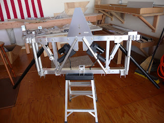
The landing gear is extended and retracted via electric motors. The travel limits of the motors are set by microswitches mounted on the bulkhead, which are contacted by a nylon disc on the retraction angle.
I know many have set their systems up with the external limit switches and have had no problems, but it struck me as having too many points for misassembly and/or problems down the road. Reading the builder's private forum I found an option for internal limit switches and decided to go that route on my build.
To become familiar with the gear mechanics I built my bulkhead stock up to the wiring of the system. I was very conscious of a post by a highly experienced and regarded builder, his comments regarding the need for positive overcenter of the retraction angles, and a ferocious debate about collapsed gear and the amount of overcenter needed for safe operations because the bulkhead is not rigid, it flexes and stretches during ground operations such as touchdown, or running over bumps in an unpaved runway.
I had the following amount of overcenter in my stock build:
9 mm on right
7 mm on left


I’m not an engineer and I know the perils of an uneducated person making assumptions. But to my uncalibrated Mk I eyeball the left gear overcenter was borderline and the right gear was not far enough. While I do not plan to do extensive rough field operations I do operate off a single runway airport with a good amount of airline traffic, so having a gear failure would be a major inconvenience to airport and airline operations.
The other problem I had with the supplied actuators was the 4.00” stroke. On the retraction cycle/extension of the ram this far exceeds the amount of travel available, and a failure of the voltage cutoff would result in the ram forcing the gear system into the lower bulkhead. There is a clutch in the system which would let the motor continue to run while disengaging it from the jackscrew, but I'm not sure how long the motor is certified to continuously run in these conditions.
Again, being a new builder and not an engineer I don’t know if this has ever happened and what the consequences might be. However, being a firm believer in Murphy’s Law I want to try to minimize any potential failures. (In 21 years of flying I’ve never had an engine failure, but I still study and practice my engine failure procedures.)
On advice of others I ordered Warner linear actuator K2P1-2G20-12V- BR-03.75 from my local dealer. On receipt of the new units I attempted to match them to the stock LSX gear setup. I found the gear extension overcenter amounts to be the same as with the stock units, but the new units still extended too far by approximately 0.5”. Had I ordered a 3.25” stroke the amount of overcenter would still have been questionable.
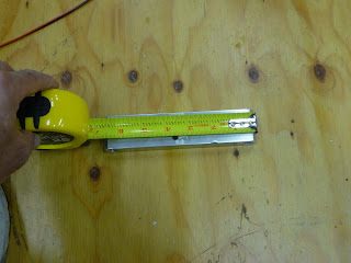
Removing the actuator mount plate gave easy access to try to determine a new position to mount the actuator. Using Paul Hewitt's idea I made 2 pieces of wood matching the extension and retraction lengths of the actuators. While I made them out of scrap wood in retrospect I should have made them of 1” dowel to match the actuator. I drilled 0.5" holes in each end and attached a clevis to the end of each, trying various positions of the clevis location in relation to the bulkhead gusset.


Using the stock position of the clevis I was unable to find a suitable location. However examination showed that the attachment point of the clevis was not centered on the retraction bar and was offset by 0.25” from the center.

Reversing the orientation of the retraction bar resulted in the clevis being located in a position that gave full extension of the actuator for the gear retraction and what may be adequate overcenter. A bit of material must be removed from the actuator mount plate.

The new position of the actuator allows full extension of the actuator for the retraction cycle without damage to the lower bulkhead cross tube in the event of failure of the internal limit switches, and an increase in the amount of overcenter of the retraction angles.


The new amount of overcenter is:
15 mm on right
16 mm on left
I'm more comfortable with this than the stock LSX setup, but I'd like to ask for any and all comments from the more experienced builders here.


Lest we forget....
Thanks Dad.

Ralph Kessinger
Y/1C USN (RET)
1946-1966
It's said that a little knowledge is a dangerous thing, and the mark of a wise man is the ability to admit he was wrong. When I made this post the SeaRey was using a "tubed" bulkhead, and that was revised in the spring of 2011 to a more rigid "webbed" or "gusseted" bulkhead that provides a more secure mount for the landing gear. After some argument with Progressive Aerodyne about a clause in my contract that entitled me to free upgrades/changes to my kit until it was LSA certified, I installed the new bulkhead in March 2011.
In 2012 I began getting build advice from long time SeaRey builder Jim Ratte of Recreational Mobility, who patiently showed me the flaws in the logic of the process in this post, and that by going with this much overcenter I was transferring the load into the gear motor, which would eventually cause damage and failure of the gear system. He also had a long talk with me about the internal vs external limit switches, and while a difficult decision I've decided to go back to the external limit switches, and the original gear mount location.
I thought about deleting this post, but decided to leave it for build history, and for those who may think of doing the same thing.
Steve
The landing gear is extended and retracted via electric motors. The travel limits of the motors are set by microswitches mounted on the bulkhead, which are contacted by a nylon disc on the retraction angle.
I know many have set their systems up with the external limit switches and have had no problems, but it struck me as having too many points for misassembly and/or problems down the road. Reading the builder's private forum I found an option for internal limit switches and decided to go that route on my build.
To become familiar with the gear mechanics I built my bulkhead stock up to the wiring of the system. I was very conscious of a post by a highly experienced and regarded builder, his comments regarding the need for positive overcenter of the retraction angles, and a ferocious debate about collapsed gear and the amount of overcenter needed for safe operations because the bulkhead is not rigid, it flexes and stretches during ground operations such as touchdown, or running over bumps in an unpaved runway.
I had the following amount of overcenter in my stock build:
9 mm on right
7 mm on left


I’m not an engineer and I know the perils of an uneducated person making assumptions. But to my uncalibrated Mk I eyeball the left gear overcenter was borderline and the right gear was not far enough. While I do not plan to do extensive rough field operations I do operate off a single runway airport with a good amount of airline traffic, so having a gear failure would be a major inconvenience to airport and airline operations.
The other problem I had with the supplied actuators was the 4.00” stroke. On the retraction cycle/extension of the ram this far exceeds the amount of travel available, and a failure of the voltage cutoff would result in the ram forcing the gear system into the lower bulkhead. There is a clutch in the system which would let the motor continue to run while disengaging it from the jackscrew, but I'm not sure how long the motor is certified to continuously run in these conditions.
Again, being a new builder and not an engineer I don’t know if this has ever happened and what the consequences might be. However, being a firm believer in Murphy’s Law I want to try to minimize any potential failures. (In 21 years of flying I’ve never had an engine failure, but I still study and practice my engine failure procedures.)
On advice of others I ordered Warner linear actuator K2P1-2G20-12V- BR-03.75 from my local dealer. On receipt of the new units I attempted to match them to the stock LSX gear setup. I found the gear extension overcenter amounts to be the same as with the stock units, but the new units still extended too far by approximately 0.5”. Had I ordered a 3.25” stroke the amount of overcenter would still have been questionable.
Removing the actuator mount plate gave easy access to try to determine a new position to mount the actuator. Using Paul Hewitt's idea I made 2 pieces of wood matching the extension and retraction lengths of the actuators. While I made them out of scrap wood in retrospect I should have made them of 1” dowel to match the actuator. I drilled 0.5" holes in each end and attached a clevis to the end of each, trying various positions of the clevis location in relation to the bulkhead gusset.


Using the stock position of the clevis I was unable to find a suitable location. However examination showed that the attachment point of the clevis was not centered on the retraction bar and was offset by 0.25” from the center.


Reversing the orientation of the retraction bar resulted in the clevis being located in a position that gave full extension of the actuator for the gear retraction and what may be adequate overcenter. A bit of material must be removed from the actuator mount plate.

The new position of the actuator allows full extension of the actuator for the retraction cycle without damage to the lower bulkhead cross tube in the event of failure of the internal limit switches, and an increase in the amount of overcenter of the retraction angles.


The new amount of overcenter is:
15 mm on right
16 mm on left
I'm more comfortable with this than the stock LSX setup, but I'd like to ask for any and all comments from the more experienced builders here.


Lest we forget....
Thanks Dad.

Ralph Kessinger
Y/1C USN (RET)
1946-1966