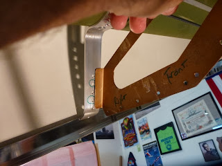
Unless you put an insert all the way down into the outer tube, you can't tighten the nut down enough to immobilize the bracket, and it could twist, allowing the pulley guard to impinge on the cable.
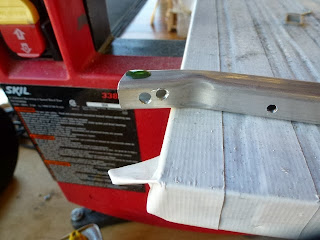
The solution (no longer mentioned in the assembly manual, for some reason) is to drill the outer tube and insert an ABL6-8 through the hole with an aluminum spacer inbetween.
Since my hull was already assembled, I couldn't get a regular right angle drill into the narrow gap. Hal from the Heritage Flight Museum came to the rescue again, with a very cool drill.
Time to start putting the fairings over the tail boom, we're quickly coming to the end of the building phase and moving into the finishing.The boom tube flexes at the transom during flight and landings, so fairings are attached to the fuselage at the top of the boom at the fin to allow this flex, yet cover her derriere.
Before you covering things up, take several moments to make sure everything is sealed, safety wired, cotter pinned, etc.
The boom tube cover angles are attached, but only the rear half. I wondered why not go all the way down, but there's a reason.
Next, attach them at the transom. It's funny talking to builders of SeaReys and other homebuilts, some hate doing fiberglass work and some love it, same thing for metal work. I tend to like fiberglass, because if you mess up it's generally nothing some glass and resin won't hide. But if you mess up a piece of metal....
Per the manual, next you're supposed to cut the slot for the Upper Tail Boom Support. We will be returning to this subject, in retrospect it should be done later. Following the manual is not always right.
A little optional fine tuning, the manual doesn't call for it but I decided to notch the aft portion of the fairing around the tail post to make the whole fairing parallel to the lower fin rib. Saw this done on other SRs, and it's another thing I am shamelessly copying. (I just found some posts dating back to the Classic that showed the sheet metal could cause cracking of the tail post if this is not done and the fairing is butted against it, so looks like a good call.)
Notching the fairing was easy to do, the post has a 1" radius and my sander has a 2". Careful application of fairing to sander makes a graceful curve, which can then be transferred to the other one.
After that punch, drill, and deburr the fairing every 2.5", then repeat in place on the boom tube.
The manual calls for slots to be cut in the aft end of the piece for the Upper Tail Boom Support, but their measurements are off. In retrospect what would be better is to hold off cutting the slots until after the fairing is mounted with clecos, then simply rotate the support up to the fairing, mark and cut. I ended up having to enlarge it by about 3/8" on the top but it's nonstructural and is mostly hidden under the elevators. I thought about cutting a new piece but worried about messing up the elevator reversing horn slot (that is visible at the front), so I decided to let it be.
Then rivet the fairings in place.
My kit is #509, and while there is no official count of how many SRs have been completed and are flying, a rough guess is well over 200 around the world. (Long before Richard joined the group SeaRey pilots were already known as Seagulls, since they tended to travel in groups, show up wherever there was food, eat it all and then fly away leaving only crumbs in their wake.)
Deciding where to follow the manual and where not to is a delicate process. When I put my deposit down in September 2009 I was told the assembly manual would be finished in 6 months, and the airplane LSA certified within a year. While the SeaRey "Classic" has been around since the mid-90s, the instructions were mostly just drawings that served as guidelines, and my hat is off the to those who have built the airplane before me.
The company has been updating the manual, but they're doing an extremely poor job of getting updates to builders. I can partially understand since the 912 version is certified but the 914 version is still undergoing testing, and there's no sense in releasing updates that may change. But I'm told there are now 37 sections to the Build Manual, I've only got 27, and those came from the unofficial builders forum. We've been told to contact Progressive Aerodyne for the updated sections, but inquiries by myself and others have only been met with silence. Frustrating, to put it mildly.
/end rant
The reason I bring this up is in the previous step I followed the manual and ended up miscutting the slot for the Upper Tail Boom Support. The next step calls for the attachment of two cover plates that hide the fairing/turtledeck junction. I decided not to attach them at this point because I wanted to paint the fairings first, but read on to see why you should follow the manual in this situation.
First, Osp was gently rotated to rest on her nose. When the Rotax 914 arrives there will be a large amount of weight aft of the wheels, but for now she balances evenly on her gear and the tail can be lifted with only a few pounds of force. In the past I had attached a few sandbags to the tail to hold it down, but with the fairings attached I had to undo them. I'm working on another project that required me to sit in the cockpit and forgot about the balance, and when I climbed in I was startled by Osp slowly nosing over. Nothing hurt but my pride, luckily, and hopefully she will never see this position after landing.
Even with her tail up it's still an awkward reach, and the control and
tailwheel cables kept catching the hairs on my arms and head. (Can't
really see it here but I resorted to my old hippie days and have my hair
tied back with a bandana.) Reading the assembly instructions, I thought
this would be a simple task I could knock out in a day. Three days later
I finally finished it. Read on for all the fun.
We're going to be installing the splashguard to the bottom of the fairings, which will tie both sides together. Had I followed the manual the cover plates would have been holding the fairings down, but without them I used some velcro straps.
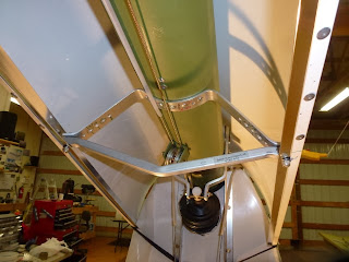
The splashguard is a v-shaped piece of aluminum. It serves to protect the control cables and deflect water from the inside of the fairings. The manual calls for it to be placed close to but not against the transom angles, so I used a piece of cardboard to set the spacing.
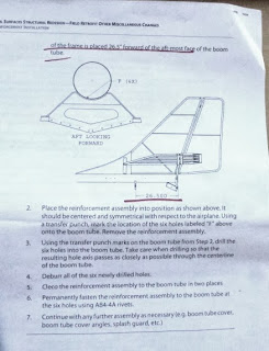
This is NOT mentioned in the manual but is very important. The aft end of the splashguard MUST be more than 26.5" forward of the aft end of the boom tube. If it is closer, the tailwheel won't have room to retract. (This is a page from the retrofit kit I was sent back in 2011.)
You're told to set the location for the aft support bracket by temporarily putting the splashguard in place, then riveting the bracket in place.The manual calls for 4 rivets, the retrofit instructions call for 6. Whaddya do?
Then the shear web is fitted in place. The aft support bracket is a thick chunk of metal, no chance of distorting it while mounting the thin shear web.
Next the aft splash guard support is fitted. But Hey, guess what? The holes don't match, and the aft support bracket can't be pulled down to fit since the shear web is bolted in place. The support is also too stiff to bend into place. There's really only one solution: take the web off, force the bracket and support together and remount the web, using the existing holes if possible.
Yup, no way to ream these holes to make it fit,
gotta drill new ones.
Back to the drawing board. If you look closely on the sides of the aft support bracket you'll see 4 hole/side, and only 2 are used. I redrilled the shear web to use the other two holes.
With the support and bracket bolted together I refitted the shear web to the bracket, clecoed and riveted it to the support. The manual shows the web attached to the bracket with the bolts inserted from below and the nuts on top, I couldn't see a reason for this so I went back to the conventional way of inserting the bolts from the top.
Before riveting, the shear web got a quick trip to the sander to remove the overhanging lip.
Kinda funny to look back and see the light changing in the photos from daylight with the doors open to later in the night with the doors closed. It was a long couple days. Frustrating when you have a problem, happyhappyjoyjoy when it's solved. Ahhhh..... kitbuilding.
Back to the spashguard. With the rear bracket in place it's time for the front. The manual calls for the splashguard to be riveted to the aft bracket, then you're supposed to fit the front bracket in place, reaching up inside the front where there is no access. I tried. Not gonna happen.
Instead a clecoclamp held the front support in place
while I moved the splashguard fore and aft to set the final spacing. There was actually a lot of side-side room between the splashguard and the fairings, leading me to believe there's a conflict between having it forward near the transom support angles where it doesn't fit, or having it back far enough so it fits side-side but leaves a gap at the front. I decided to set it at the forward location and we'll get to the side-side play later. (No, it's not possible to pull the fairing sides down to fit the guard without distorting them.)
With the front support in place, it was time to take a look, and here's why I should have put the cover plates in place. If I had installed them they would have held the fairings down.
Another problem is that the splashguard forward support is 1/2" too wide, and 1/4" needed to be trimmed from each side.
With the cover plates in place and the forward support trimmed, the fairing set into shape fine. Note that the cover plate is only riveted at the front, the manual calls for a rivet in the top aft corner of the cover plate into the fairing, defeating the purpose of allowing the fairing to slide in and out during turbulence, landing, etc.
With the front in place now it's time to rivet the splashguard to the aft support. Earlier in the assembly (I'll add those pics when I get home) the cover angles are riveted to the rear of the fairing. Had the splashguard been wide enough to reach all the way across, the fairing, cover angle, and splashguard could have been riveted together. However, in my build the splashguard was not wide enough to do this, so instead the fairing was riveted to the cover angle, then the splashguard riveted to the cover angles in a staggered sequence. It's actually a pleasing look that will never be seen.


